Using Pulse Width Modulation (PWM) on an RGB LED and the Raspberry Pi
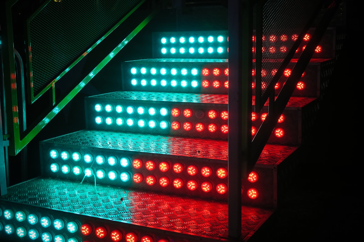
If you buy a kit with random LEDs, wires, switches, etc, you’re likely to end up with one or two of those funky little LEDs that appears to be white, and has 4 wires instead of 2. I had set mine aside and made a mental note to figure it out later – well, that time has come!
If you'd like to follow along, you can find the code on GitHub.
It’s a special kind of LED that consists of 3 separate LEDs – red, green and blue. By adjusting each color independently, you can create any color (similar to how a TV works). By lighting all 3 in the right proportions, you can even create white.
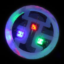
If you haven’t played around with single-color LEDs yet, you may want to try that first, although the process for an RGB LED is hardly more complicated.
Laying Out the Circuit
While it’d be quickest to just plug an LED into a breadboard and connect the wires directly to 3.3v and ground, that’s the kind of fun that’s short-lived and usually ends in tears.
So let’s take a few minutes to collect some information about the RGB LED, calculate the necessary resistors, and then lay it all out on a breadboard the right way. After all, nobody likes burnt Pi.
Ohm’s Law, and Selecting the Right Resistors
Placing a resistor in your circuit when you’re using an LED is always a good idea, but how do we know which one to use? Too much resistance, and the LED will appear very dim or won’t light at all. Too little resistance, and the LED burns out and possibly damages the GPIO pin (or worse).
When you bought the LED, did it come with a data sheet? It’ll look something like the image below, which I pulled out of one of the SparkFun data sheets for an RGB LED. If it didn’t come with one (mine didn't), the values below are pretty typical and safe to use, at least as a starting point (more on that later).
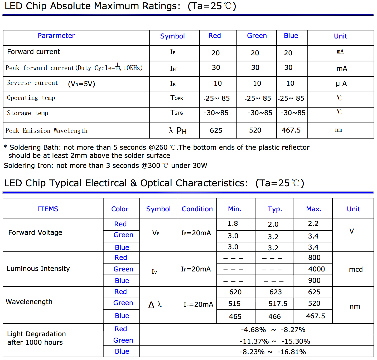
There’s a lot of info there, but the values we’re interested in are “forward current” and “forward voltage”. Oh, and you know the Raspberry Pi outputs 3.3v, right? That’s important too.
There’s a handy little equation called Ohm’s law that’s going to help us out. You might want to read this basic overview of voltage, current and resistance from SparkFun. (They forgot to mention subtracting the LED’s forward voltage from the incoming voltage, which results in selecting a higher value resistor than necessary. That’s better than a lower resistance than necessary, but still not optimal.)
Resistance = Voltage / Amperage
- The total voltage is our incoming voltage minus typical forward voltage
- The amperage is the forward current divided by 1000 (since the value in the chart is in mA, but we need amps)
Using that, we can calculate our resistors:
- Resistor for Red: (3.3v – 2.0v) / .02A = 65Ω
- Resistor for Blue: (3.3v – 3.2v) / .02A = 5Ω
- Resistor for Green: (3.3v – 3.2v) / .02A = 5Ω
If you don’t want to memorize Ohm’s Law, bookmark one of the many calculators out there, like this one or this other one.

Hopefully you’ve got a nice variety of resistors. If not, Amazon's got some nice little sets. The closest matches I have that don’t go under the amounts calculated above is 100Ω and 10Ω, so I started with those.
Designing the Breadboard
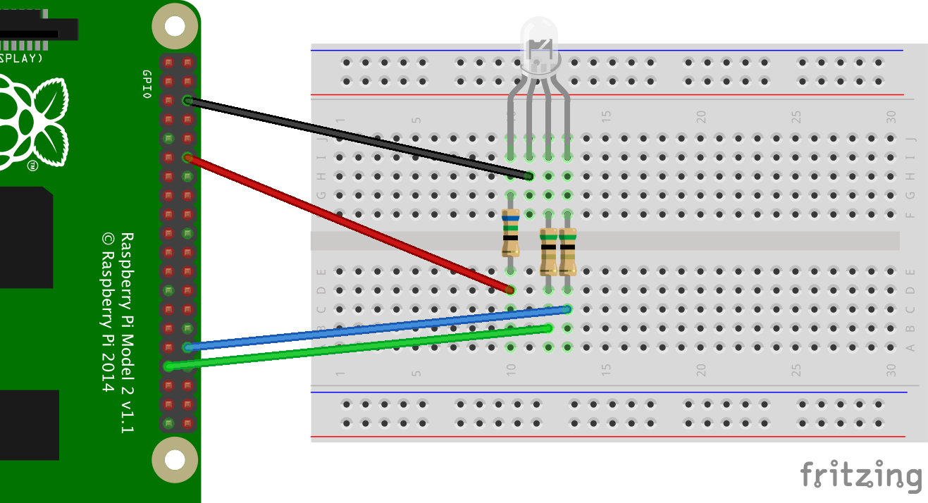
Take a close look at that LED – notice the four wires are not all the same length. The longest is the singular cathode, and it connects to ground. The other three (anodes) connect to red, green and blue, assuming you have your RGB LED oriented as in the image below.

Now we can lay everything out on a breadboard. Here’s the layout I chose, using GPIO18, 12 and 13 for red, blue and green respectively.
And a couple photos, if that makes it easier to see…
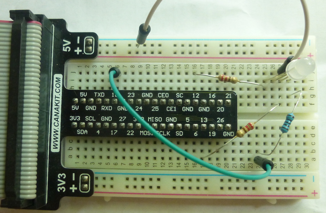
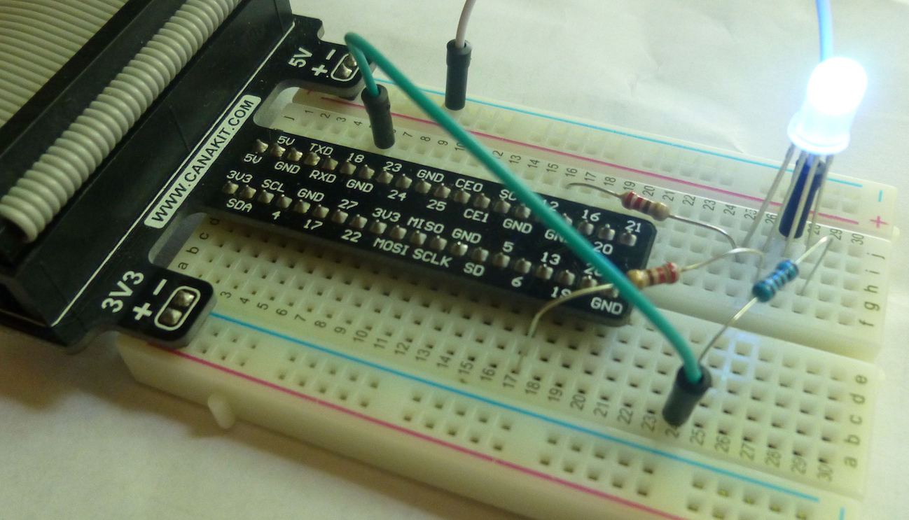
I like using the T-cobbler that comes from the Canakit package, which takes up some of the board but is more convenient than a bunch of wires leading directly back to the GPIO pins. Plus, I have a half-dozen breadboards, so I can unplug the cobbler from one project and set it aside, and connect it to another breadboard holding a different project. Like I said, convenient.
Running the Python Scripts
Here are a couple of quick scripts to demonstrate the RGB LED. You can also find the full source on GitHub.
Script 1: Flash Different Colors
This first script just turns on and off different colors randomly, so you can see some of the different mixing going on.
import RPi.GPIO as GPIO
import threading
import time
import random

PINS = [12,33,32]  # R,G,B


def main():
    try:
        GPIO.setmode(GPIO.BOARD)
        GPIO.setup(PINS, GPIO.OUT, initial=GPIO.LOW)
        print("\nPress ^C (control-C) to exit the program.\n")
        while True:
            select_and_set_next_pin()
            if all(GPIO.input(pin) == GPIO.LOW for pin in PINS):
                select_and_set_next_pin()
            time.sleep(0.75)
    except KeyboardInterrupt:
        pass
    finally:
        GPIO.cleanup()


def select_and_set_next_pin():
    next_pin = PINS[random.randint(0, 2)]
    GPIO.output(next_pin, not GPIO.input(next_pin))


if __name__ == '__main__':
    main()
Script 2: Use PWM for Smooth Color Transition
Once you have an LED wired up with a resistor, it’s either on or off – you can’t dim it or brighten it without changing the resistor. But you can make it appear to be dimmer or brighter, by telling the Pi to quickly blink it on and off hundreds of times a second (frequency), and further by telling it how long to keep it on and off each time it blinks (duty cycle).
That’s called pulse-width modulation, or PWM. The RPi.GPIO library can simulate PWM with any of the GPIO pins we’d normally use to power an LED. Here’s a sample implementation from their documentation.
The following script is more interesting than the first one. It leaves all the colors enabled, but adjusts their duty cycle separately, in separate threads. The effect is that all 3 colors fade in and out independently, creating all possible colors.
First I set the pins to use for red, green and blue (R,G,B) and set them LOW by default. When they’re set to HIGH, they’ll send power to the LED and light it up. There are three separate threads running infinite loops, each exercising PWM on a separate color at a slightly different speed.
import RPi.GPIO as GPIO
import threading
import time
import random

R = 12
G = 33
B = 32

PINS = [R,G,B]


def initialize_gpio():
    GPIO.setmode(GPIO.BOARD)
    GPIO.setup(PINS, GPIO.OUT, initial=GPIO.LOW)


def color_test(channel, frequency, speed, step):
    p = GPIO.PWM(channel, frequency)
    p.start(0)
    while True:
        for dutyCycle in range(0, 101, step):
            p.ChangeDutyCycle(dutyCycle)
            time.sleep(speed)
        for dutyCycle in range(100, -1, -step):
            p.ChangeDutyCycle(dutyCycle)
            time.sleep(speed)


def color_test_thread():
    threads = []
    threads.append(threading.Thread(target=color_test, args=(R, 300, 0.02, 5)))
    threads.append(threading.Thread(target=color_test, args=(G, 300, 0.035, 5)))
    threads.append(threading.Thread(target=color_test, args=(B, 300, 0.045, 5)))
    for t in threads:
        t.daemon = True
        t.start()
    for t in threads:
        t.join()


def main():
    try:
        initialize_gpio()
        print("\nPress ^C (control-C) to exit the program.\n")
        color_test_thread()
    except KeyboardInterrupt:
        pass
    finally:
        GPIO.cleanup()


if __name__ == '__main__':
    main()
Apparently there is one pin (GPIO18) that allows hardware PWM, and maybe GPIO12 too, but I’m unclear on that. Then you’d need to use something like the Adafruit 16-Channel 12-bit PWM/Servo Driver – I2C interface to turn the pin into 16 pins, and the board can even be chained together.
Other libraries, like WiringPi for Python and the pigpio module, can make use of PWM using the dedicated hardware on the Pi (again, I’m not completely clear on this yet), but RPi.GPIO doesn’t support it yet. That’s okay though… for what we’re doing here, the software PWM performs just fine.
Note that the current release does not support SPI, I2C, hardware PWM or serial functionality on the RPi yet. This is planned for the near future – watch this space! One-wire functionality is also planned.
Although hardware PWM is not available yet, software PWM is available to use on all channels.
Fine-Tuning the Resistors
I mentioned earlier that the values in the chart were good starting points. Unless you’ve got the correct data sheet (and even if you do…) you might find the resistors need a bit of tweaking. I used Ohm’s Law to calculate the ideal resistors for my LED (as close as I could), and they worked okay. I let the above script run for about a half-hour, and neither the LED nor the resistors started heating up.
But I noticed something. When all 3 colors were on, the “white” light that should have produced had a distinctly blue hue to it, like one color was slightly overpowering the others. I played around with a few different resistors, trying to increase the resistance slightly, and ended up putting a 220Ω resistor on blue and green, while leaving the 100Ω resistor on red. Now the color looks white.
You may find you have to do the same. Here’s someone else who had to adjust his resistors, calculating 70 for red and 0 for green, but then finding that 0 for red and 220 for green worked better. I would’ve been hesitant to decrease resistance below the calculated amount for fear of burning something out, but he was using a multi-meter to test the voltage so he probably knows what he’s doing better than me. :)
Quick Note About Reverse Polarity
Apparently (from what I’ve read) it’s possible for some RGB LEDs to have a single anode and one cathode per color, which is the opposite from everything I’ve described so far. If that’s the case, your LED won’t light up when you lay things out like I’ve got them. You may need to connect the single anode to 3.3v (instead of ground), then adjust the above scripts to set the pins HIGH initially, then set them LOW to make them light up.
I just looked up RGB LEDs on Amazon, and came across a set that appears to have this issue. Be sure the read the comments, as people will probably note when they have an issue with them.
Video or It Didn’t Happen
And finally, a video showing it in practice:
Further Reading
For those that just can’t get enough, here’s some resources I stumbled on while researching LEDs and all their related goodness…
- Voltage, Current, Resistance, and Ohm’s Law, I’d recommend reading the entire article – it’s very helpful.
- Basics: Picking Resistors for LEDs
- LED Center
- Can I use the GPIO for pulse width modulation (PWM)?
- Dim an LED using Pulse-Width Modulation with the Raspberry Pi, a YouTube video demonstrating PWM
That’s it! Good luck with your own RGB LED experiment!
Questions? Suggestions on how to improve this? If you found this useful, I’d love to hear from you… leave a comment below. If you write about your own LED experience, leave a link too so I can check it out!

Comments / Reactions