
On past projects, when I’ve needed multiple LEDs (like in my Simon clone), I just connected each individual LED to its own GPIO pin. I was aware that current had to travel through the LED in one direction and that it wouldn’t light if wired in the other direction, but it hadn’t occurred to me to take advantage of that fact.
This is where charlieplexing comes in. We can arrange multiple LEDs such that we use the minimal number of GPIO pins possible.
Connecting 2 LEDs to 2 GPIO pins#
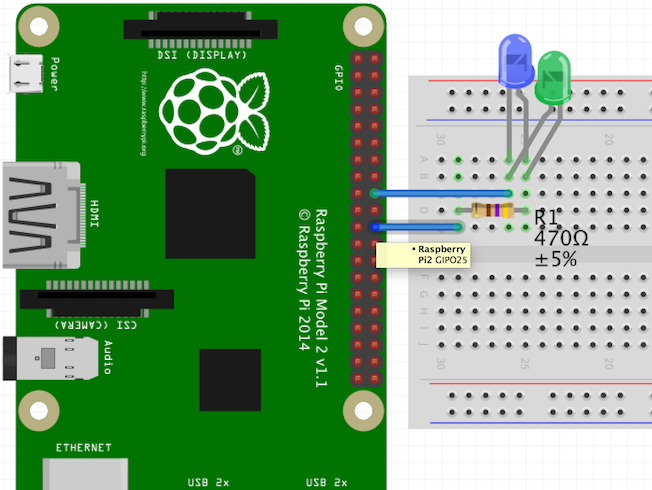
If we connect 2 LEDs to the same 2 GPIO pins, but with their anode and cathode reversed from one another, then only one will light at a time. To do this, set two GPIO pins (24 and 25 in my example) to GPIO.OUT, but one to HIGH (or 1) and the other to LOW (or 0).
By flip-flopping which one is HIGH and which one is LOW, we can turn one LED on at a time, making them blink opposite each other. If we do this fast enough, the on/off switching is still taking place but so rapidly that they appear to be simultaneously “on” to the human eye.
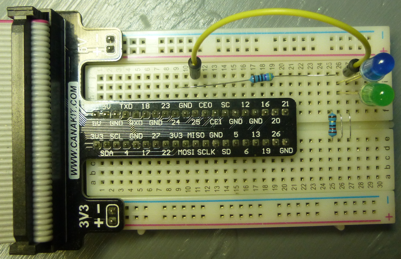
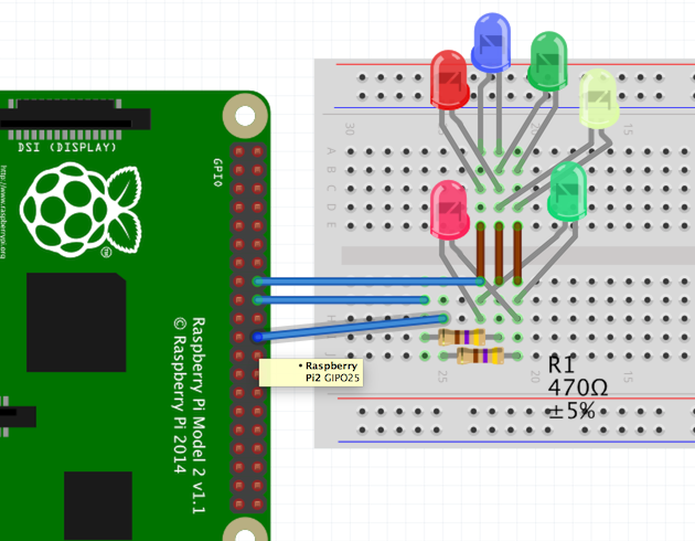
Try it out by setting up your circuit like the diagram and images below. You’ll need a couple resistors – 220 ohm is okay, 470 ohm is probably better – and a couple LEDs. I used a wire because really you only need one resistor in the path (it doesn’t matter where in the path it is – between the power source and LED, or between the LED and ground).
Once the circuit is set up correctly, run this script.
Here’s the important part – it sets the pins and flips the direction of the current every tenth of a second.
GPIO.setup(PIN_A, GPIO.OUT, initial=1)
GPIO.setup(PIN_B, GPIO.OUT, initial=0)

while True:
    GPIO.output(PIN_A, not GPIO.input(PIN_A))
    GPIO.output(PIN_B, not GPIO.input(PIN_B))
    time.sleep(.01)
Connecting 6 LEDs to 3 GPIO pins#
Connecting 2 LEDs to 2 pins doesn’t buy us anything, since we would’ve had to use 2 pins anyway.
But what if we use 3 GPIO pins? Then we need to make a change – they can’t all be set to GPIO.OUT. One pin is set to HIGH and one to LOW to turn a specific LED on. If the third pin is also set to HIGH or LOW, because of the way the LEDs are all interconnected (see the diagram below), it’s going to have a negative effect on our circuit.
Instead, the third pin needs to be set in such a way that it’s effectively removed from the circuit, and we can do that by setting it to input (GPIO.IN).
Check out the diagram below. Notice how, if pin 25 is HIGH, it affects two LEDs – the anode of both the pink and yellow LEDs are on pin 25. You can set pin 24 to LOW to light the yellow LED or set pin 23 to LOW to light the pink. But since we only want one at a time, either pin 23 or 24 has to be set to GPIO.IN so the LED connected to it won’t light up.

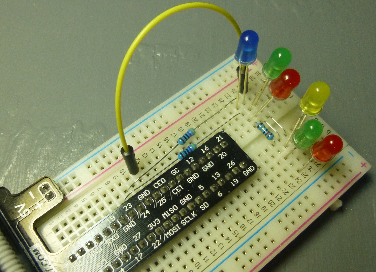
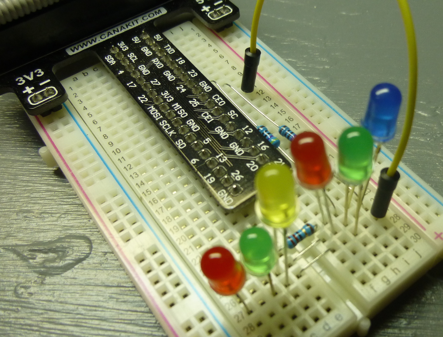
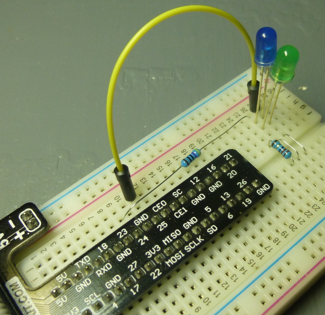
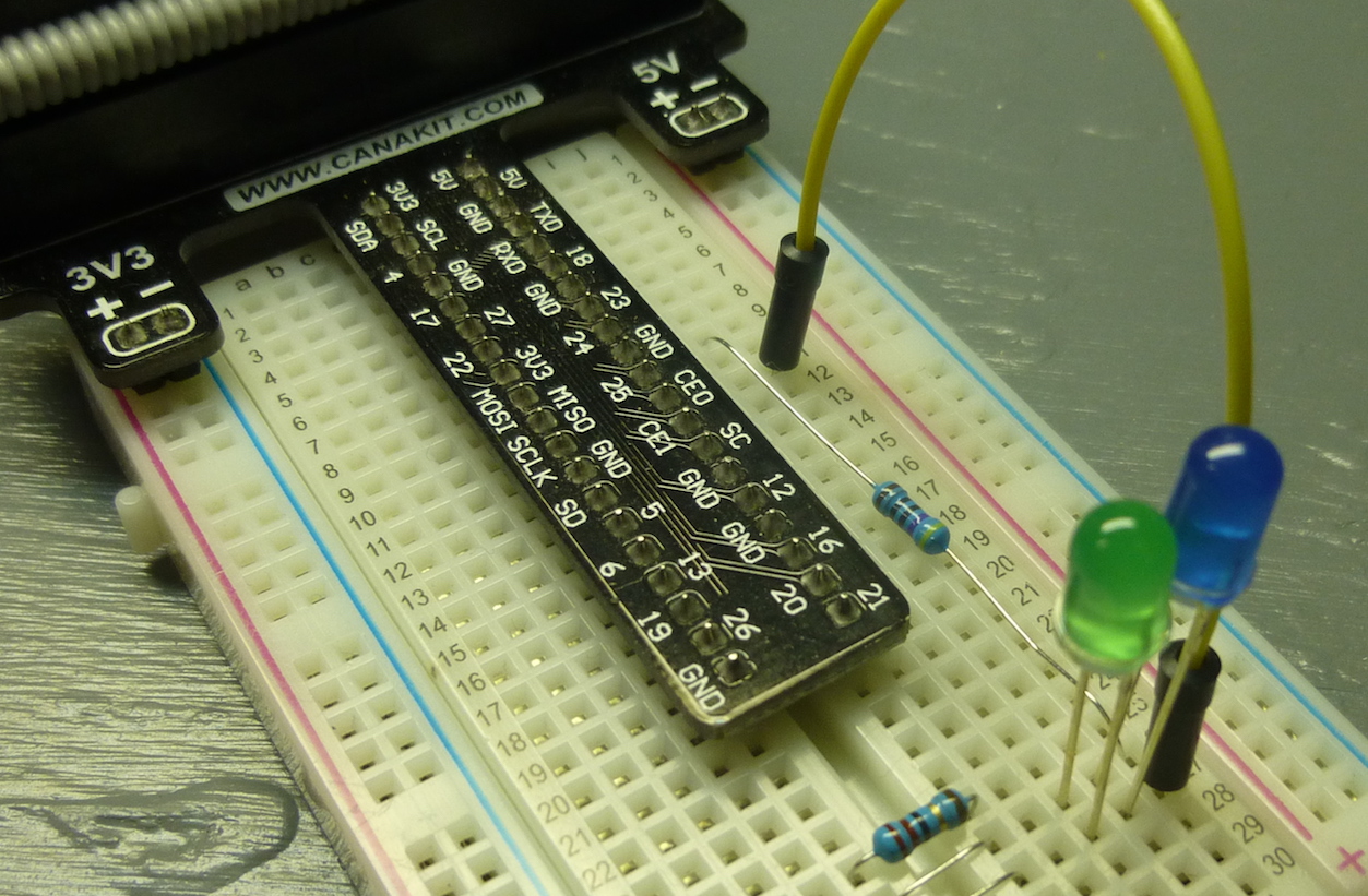
Setup a circuit like the diagrams and images above, then run this script.
The main section of the code iterates through an array that specifies which pins are input, high output and low output, and adjusts the pins every tenth of a second so that each LED is flashed on and off in turn.
while True:
    for led in LEDS:
        for idx, pin in enumerate(led):
            if pin == O:
                GPIO.setup(PINS[idx], GPIO.IN)
            else:
                GPIO.setup(PINS[idx], GPIO.OUT)
                GPIO.output(PINS[idx], pin)
        time.sleep(.1)
Seeing it in Action#
Here’s a short video I took, showing both configurations in action… and if you find this useful, or have used charlieplexing in a project of your own, or just have something to share that I left out and others should know, please share your thoughts below!